Est. 2020 · Working in accordance with ISO 9001 & ISO 45001
TechRay NDT (Pty) Ltd - home
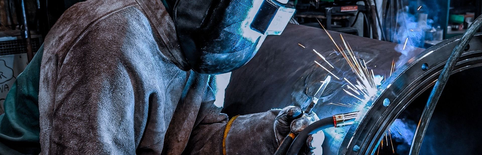
Welder working on a pipe flange joint

Home  /  Services

Non-destructive
testing services

Comprehensive non-destructive testing to detect surface, sub-surface and internal defects without damaging components. Our inspection services cover welds, plate, pipework, structures, pressure equipment, castings and forgings — performed by qualified and experienced personnel in accordance with applicable codes, standards and specifications.

How we work

The right NDT method.
The right solution.

Every inspection starts with understanding your specific requirements. We consider the material, potential defects, accessibility and applicable standards to determine the most effective NDT method for the job.

Where a project requires multiple techniques, such as Radiographic Testing (RT) and Magnetic Particle Testing (MT), we recommend the right combination from the start. This ensures accurate results, efficient inspections and no unexpected surprises during your project.

Our goal is simple: the right inspection, done right the first time.

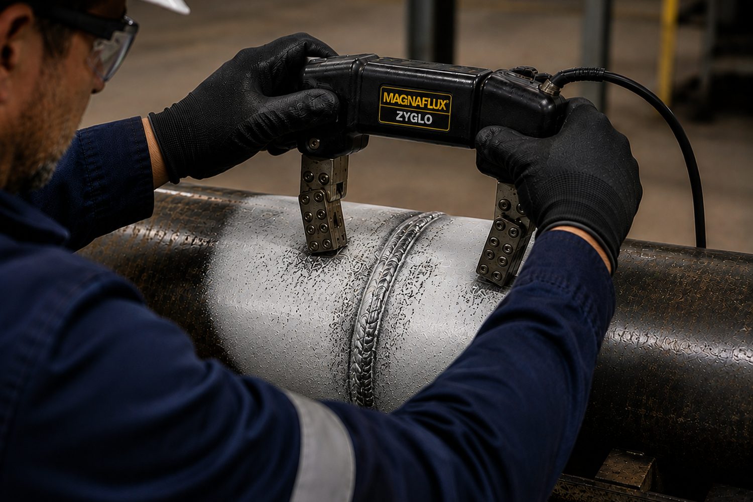
01 Magnetic particle testing (MT) with an electromagnetic yoke across a painted pipe weld
MT

Magnetic Particle Testing

Magnetic Particle Testing is a non-destructive testing method used to detect surface and near-surface discontinuities in ferromagnetic materials such as carbon steel, low-alloy steel and cast iron.

During the inspection, the component is magnetised, creating a magnetic field within the material. If a crack or other discontinuity interrupts the magnetic field, a magnetic flux leakage occurs at that location. Magnetic particles are then applied to the test surface, where they gather around the leakage field and form a visible indication of the discontinuity.
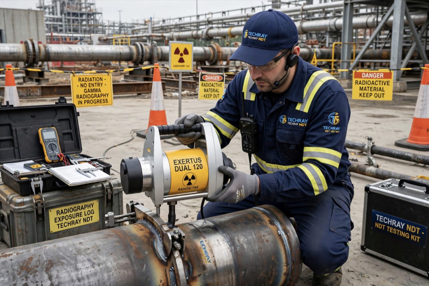
02 Radiographic testing (RT): gamma radiography set up on a pipe weld inside a barricaded radiation zone
RT

Radiographic Testing

Industrial Radiography (RT) is a non-destructive testing method used to examine the internal structure and integrity of components, welds and fabricated structures without causing damage to the material. It uses X-rays or gamma radiation to produce an image of the component, allowing internal discontinuities that cannot be detected through visual inspection to be identified.

During the inspection, radiation is directed through the component onto a radiographic film. Differences in material thickness, density or internal structure affect the amount of radiation reaching the detector, producing an image that can reveal discontinuities such as porosity, slag inclusions, lack of penetration, lack of fusion, cracks and other internal imperfections.

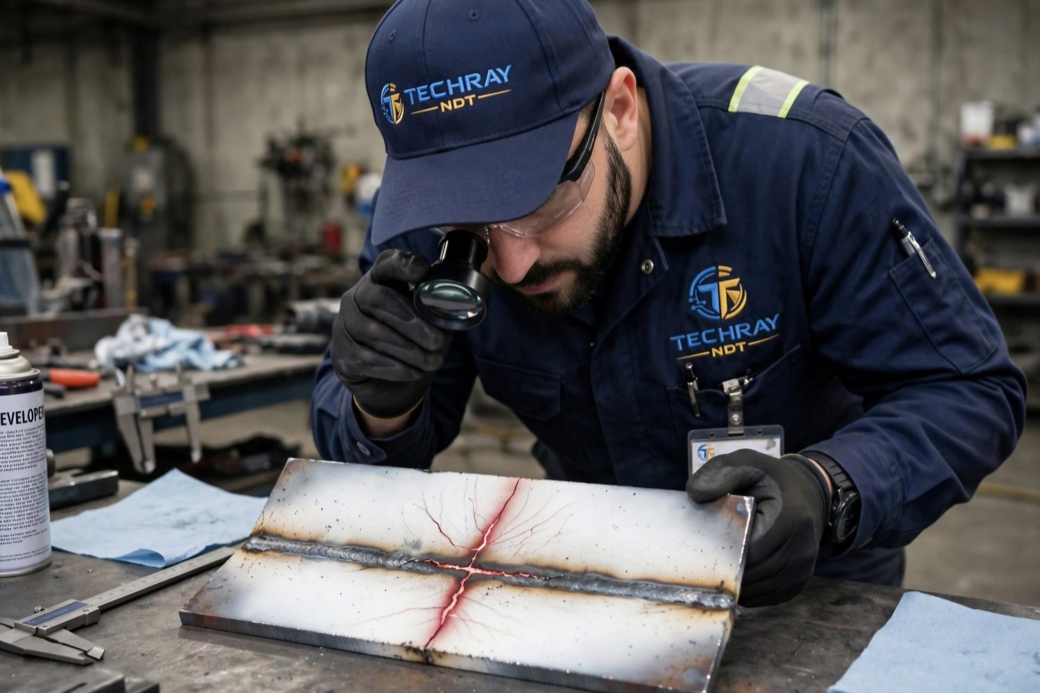
03 Dye penetrant testing (PT): red crack indications showing through white developer on a welded plate
PT

Dye Penetrant Testing

Dye Penetrant Testing, also known as Liquid Penetrant Testing, is a non-destructive testing method used to detect surface-breaking discontinuities in non-porous materials.

During the inspection, the test surface is thoroughly cleaned and prepared, after which a visible or fluorescent penetrant is applied. The penetrant is allowed sufficient time to enter any surface-breaking defects through capillary action. The excess penetrant is then removed from the surface and a developer is applied. The developer draws the trapped penetrant back out of the discontinuity, creating a clear, visible indication of the defect.

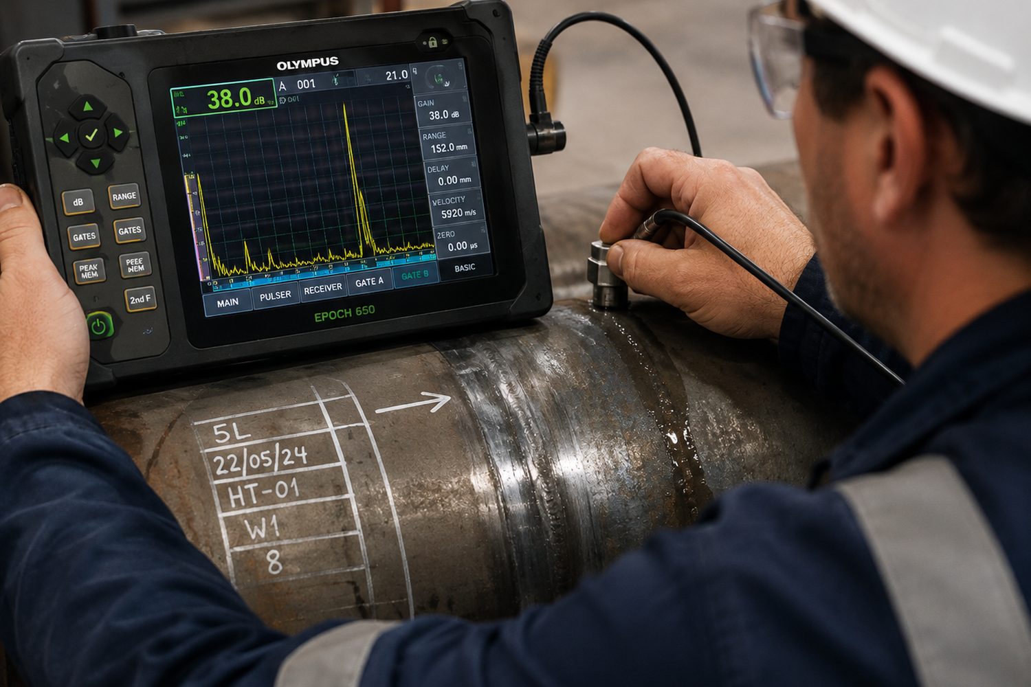
04 Ultrasonic testing (UT) of a pipe weld with a portable ultrasonic flaw detector
UT

Ultrasonic Testing

Ultrasonic Testing uses high-frequency sound waves to inspect materials for internal and surface-breaking discontinuities without causing damage to the component.

During testing, an ultrasonic probe sends sound waves into the material. As the sound waves travel through the component, they are reflected when they encounter interfaces, changes in material structure, or discontinuities. The reflected signals are displayed on an ultrasonic instrument, allowing a qualified technician to assess the location, depth and size of indications.

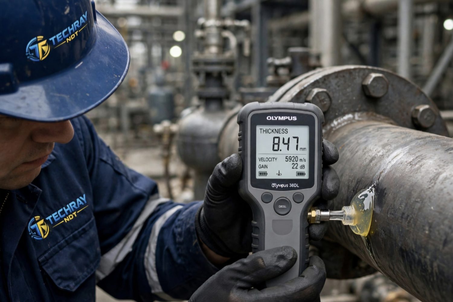
05 Ultrasonic wall thickness measurement (WT) with a thickness gauge on a flanged pipe
WT

Ultrasonic Wall Thickness Measurement

Corrosion and erosion do not announce themselves. Wall thickness measurement gives you a grid of real numbers across a vessel, tank or line — and repeated over time, a trend you can plan a shutdown around instead of reacting to a failure.

Readings are taken at referenced locations so the survey can be repeated at the next inspection interval and compared directly against the previous data set.

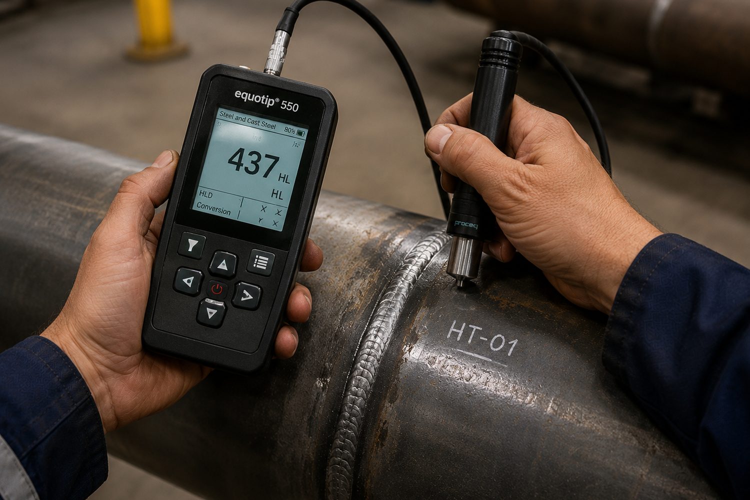
06 Hardness testing (HT) with a portable hardness tester beside a pipe weld
HT

Hardness Testing

Welding and heat treatment change the material, and hardness is the quickest honest reading of whether that change is inside specification. Excess hardness in the heat-affected zone is a defect waiting for a service load — we take the readings to the relevant hardness scale and compile a detailed report.

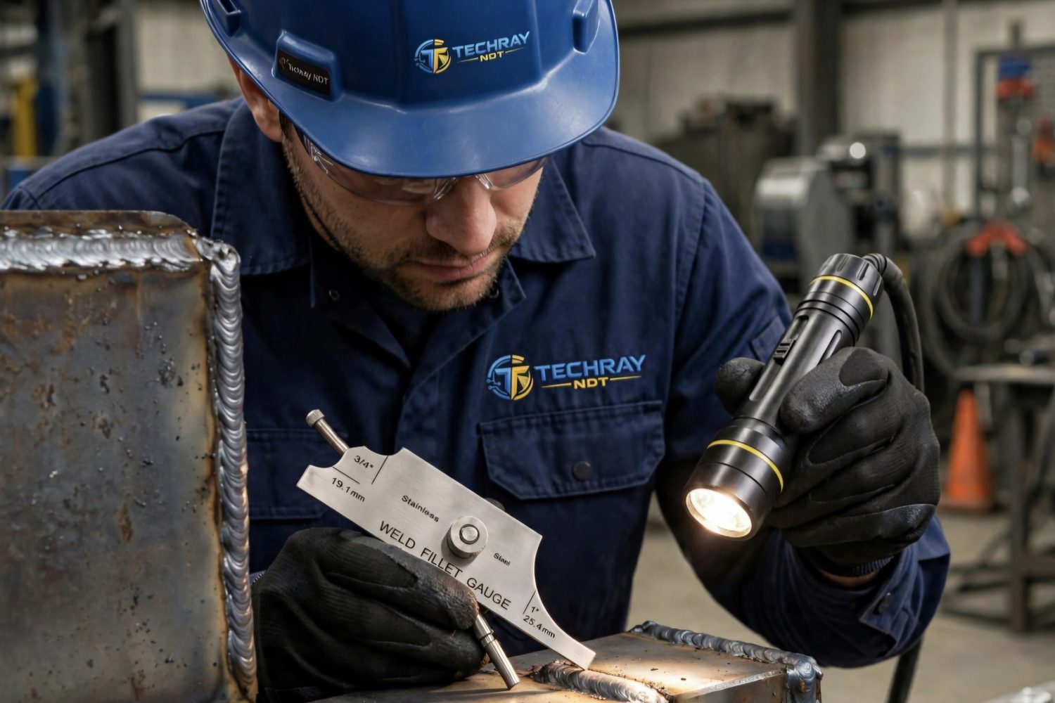
07 Visual testing (VT) of a fillet weld with a weld gauge and inspection torch
VT

Visual Testing

Visual Testing is the oldest and most basic NDT method — and the foundation for all the others. If you cannot see a defect, you often cannot test for it properly with another method.

It is the visual inspection of a surface to find discontinuities: anything that breaks uniformity — cracks, corrosion, misalignment, weld defects, dents, wear, leaks and colour changes. It does not just mean looking with your eyes. It is a formal, codified procedure with lighting, distance and angle requirements.

Where we cannot get direct access, we use tools to bring the image to you — borescopes, for example.

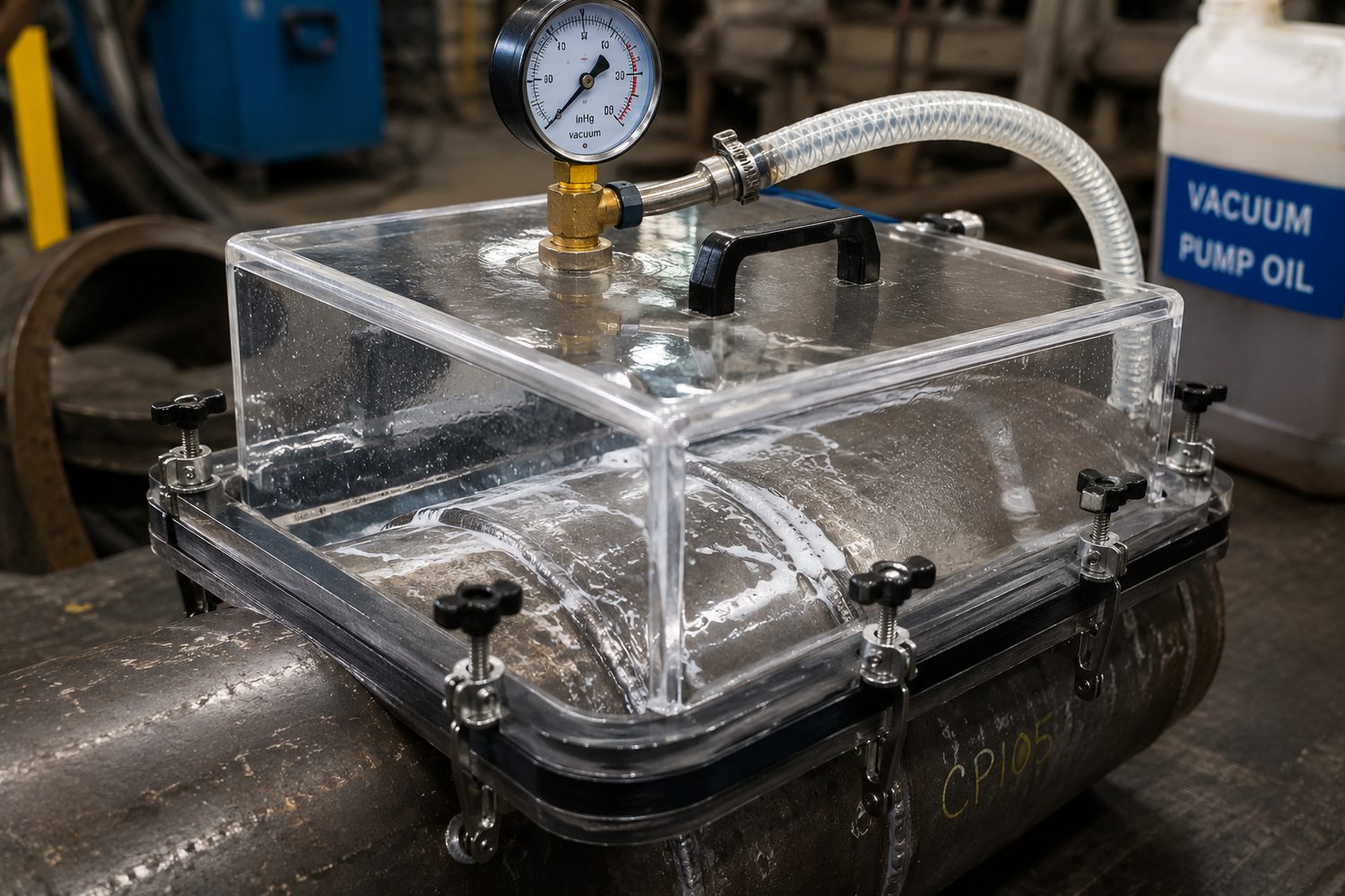
08 Vacuum box testing (VBT): a clear vacuum box with pressure gauge clamped over a weld seam
VBT

Vacuum Box Testing

Vacuum Box Testing is a leak test for welds, and one of the most common NDT methods for tanks, vessels and floors where you cannot pressurise from the back side. It checks whether a weld is completely leak-tight.

It creates a low-pressure zone on one side of the weld. If there is any hole, crack or lack of fusion, air from the outside is drawn through and you will see it as bubbles.

Principle: atmospheric pressure + soap bubbles = leak detection

Reporting

A result is only
as good as its report.

Findings are recorded against the applicable acceptance criteria, specifications and project requirements — accurate, traceable and written as legal evidence that the test was done, by whom, when, with what equipment and according to which standard. Without that, you cannot prove the component is safe.

  • Scope, method, equipment and technique recorded on every report
  • Indications located and referenced so they can be found again
  • Acceptance criteria stated — accept or reject, not "possibly"
  • Repeat inspections referenced to previous data for trending
  • Turned around promptly — a late report holds up your programme